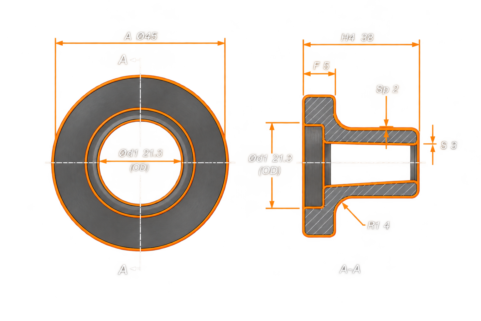
| DN |
Outside Diameter of Neck (A) |
Collar Thickness (F) |
Length (H4) |
Wall Thickness (S) |
|---|---|---|---|---|
| 10 | 17,2 | 5 | 35 | 3 |
| 15 | 21,3 | 5 | 38 | 3 |
| 20 | 26,9 | 6 | 40 | 3 |
| 25 | 33,7 | 7 | 40 | 3 |
| 32 | 42,4 | 8 | 42 | 3 |
| 40 | 48,3 | 8 | 45 | 3 |
| 50 | 60,3 | 8 | 45 | 3 |
| 65 | 76,1 | 8 | 45 | 4 |
| 80 | 88,9 | 10 | 50 | 4 |
| 100 | 114,3 | 10 | 52 | 4 |
| 125 | 139,7 | 10 | 55 | 5 |
| 150 | 168,3 | 10 | 55 | 6 |
| 200 | 219,1 | 11 | 62 | 6 |
| 250 | 273,0 | 12 | 68 | 8 |
| 300 | 323,9 | 12 | 68 | 8 |
| 350 | 355,6 | 13 | 68 | 8 |
| 400 | 406,4 | 14 | 72 | 8 |
| 450 | 457,0 | 15 | 72 | 8 |
| 500 | 508,0 | 16 | 75 | 8 |
| 600 | 610,0 | 18 | 80 | 10 |
| 700 | 711,0 | 20 | 80 | 10 |
| 800 | 813,0 | 20 | 90 | 12 |
| 900 | 914,0 | 22 | 95 | 12 |
| 1000 | 1 016,0 | 24 | 95 | 12 |
| 1200 | 1 219,0 | 26 | 115 | 16 |
| 1400 | 1 422,0 | — | — | - |
| 1600 | 1 626,0 | — | — | - |
| 1800 | 1 829,0 | — | — | - |
| 2000 | 2 032,0 | — | — | - |
| 2200 | 2 235,0 | — | — | - |
| 2400 | 2 438,0 | — | — | - |
| 2600 | 2 620,0 | — | — | - |
| 2800 | 2 820,0 | — | — | - |
| 3000 | 3 020,0 | — | — | - |
a) For flanges type 21 the outside hub diameter approximately corresponds to the outside pipe diameter and the nominal value dimensions A, N3 and R1 and their tolerances are included for guidance only.
b) To be specified by the purchaser.
c) Use is limited up to DN 600.
d) According to EN 1092-2 (Cast iron flanges) and EN 1092-3 (Copper alloy flanges), the flanges in this DN and PN may be supplied with 4 holes. Where steel flanges are required with 4 holes, these may be supplied by agreement between flange manufacturer and purchaser.
Precision Engineering. Technical Expertise. Global Supply.
