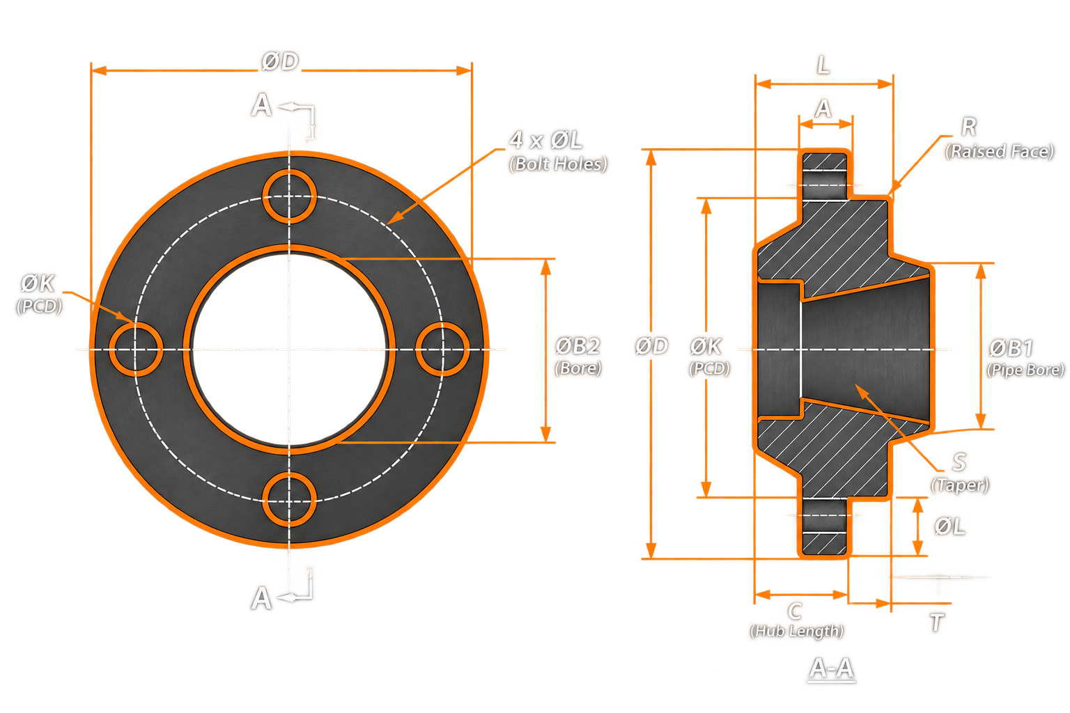
| DN |
Outside Diameter (D) |
Diameter of Bolt Circle (K) |
Diameter of Bolt Hole (L) |
Bolting Number |
Bolting Size |
Outside Diameter of Neck (A) |
Flange Thickness (C2) |
Length (H2) |
Length (H3) |
Neck Diameters (N1) |
Corner Radius (R1) |
Wall Thickness (S) |
|---|---|---|---|---|---|---|---|---|---|---|---|---|
| 10 | 125 | 85 | 18 | 4 | M16 | 17,2 | 28 | 65 | 8 | 48 | 4 | 3,6 |
| 15 | 145 | 100 | 22 | 4 | M20 | 26,9 | 30 | 68 | 8 | 56 | 4 | 5,0 |
| 20 | - | - | - | - | - | - | - | - | - | - | - | - |
| 25 | 180 | 130 | 26 | 4 | M24 | 42,4 | 38 | 90 | 10 | 82 | 4 | 7,1 |
| 32 | - | - | - | - | - | - | - | - | - | - | - | - |
| 40 | 220 | 165 | 30 | 4 | M27 | 60,3 | 48 | 110 | 12 | 106 | 6 | 10,0 |
| 50 | 235 | 180 | 30 | 8 | M27 | 76,1 | 52 | 120 | 15 | 120 | 6 | 12,5 |
| 65 | 290 | 225 | 33 | 8 | M30 | 101,6 | 64 | 135 | 18 | 158 | 6 | 16,0 |
| 80 | 305 | 240 | 33 | 8 | M30 | 114,3 | 68 | 150 | 20 | 174 | 8 | 17,5 |
| 100 | 370 | 295 | 39 | 8 | M36 | 139,7 | 80 | 175 | 25 | 216 | 8 | 22,2 |
| 125 | 415 | 340 | 39 | 12 | M36 | 193,7 | 92 | 200 | 30 | 258 | 8 | 30,0 |
| 150 | 475 | 390 | 42 | 12 | M39 | 219,1 | 105 | 225 | 35 | 302 | 10 | 35,0 |
| 200 | 585 | 490 | 48 | 16 | M45 | 273,0 | 130 | 280 | 40 | 388 | 10 | 40,0 |
a For flanges type 21 the outside hub diameter approximately corresponds to the outside pipe diameter and the nominal value dimensions A, N3 and R1 and their tolerances are included for guidance only.
Precision Engineering. Technical Expertise. Global Supply.
